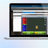
Topcon 3D-MC Edge is a flexible and cost-effective machine control solution that focuses directly on the cutting edge, attachment or another defined point of interest. It is designed primarily for rough grading and bulk earthmoving applications where dependable 2D or 3D guidance is required without the full MC-Max machine control architecture.
The system can provide indicate guidance or automatic hydraulic control for a steel cutting edge, grading attachment or defined virtual line, such as the bottom of a compactor drum. Edge supports general 2D and 3D indicate masted configurations, together with machine-specific automatic control configurations for supported dozers, graders, scrapers and compact-tracked loader attachments.
Every Edge installation uses a single TS-i4 inertial sensor to monitor the movement and orientation of the blade, attachment or selected point of interest.
Edge is built around the modular Topcon MC-X platform and can be configured using GNSS, LPS, laser, sonic or slope positioning. Cab Kit components can also be transferred between prepared machines, helping contractors extend machine control across a fleet without purchasing a complete system for every machine.
Cab Kit Components
- GX-90 touchscreen display for a wired installation or the GX-10W or compatible for a wireless installation.
- MC-X1 machine control controller.
- GR-i3 or GR-i3F GNSS position sensor for a GNSS configuration.
- A7X machine prism for an LPS configuration.
- UHF radio, cellular modem or network correction hardware selected for the final configuration.
- Compatible Topcon robotic total station or LN-Series 3D positioning system where LPS operation is required.
Wiring Kit Components
- Single TS-i4 inertial sensor mounted on the blade, attachment or rigid moving member being positioned.
- Machine-specific CAN or non-CAN wiring harness.
- M12 cables, splitters and in-line terminators used by the Edge wiring architecture.
- MC-X1 cable to power screen (GX-90) and optional radio.
- Vibration pole and blade mount.
The TS-i4 and GNSS receiver or prism must be installed on parts of the machine that move together. This allows Edge to accurately monitor the position and movement of the selected cutting edge or point of interest.
Topcon Sitelink3D Online Data Transfer and Remote Access
Sitelink is Topcon’s online, cloud-based data management and remote access platform.
To access Sitelink, users must first create a free MyTopcon account at www.topconpositioning.com.
Topcon machine control systems are supplied with a Topcon data SIM. Once activated, these SIM cards enable network connectivity and can be paired with Sitelink for remote access and file transfer (for more info on this, contact us). Sitelink connectivity is currently run on a per-point basis. Points can be purchased from our website and activated on My Topcon. Once Sitelink points have been activated, the Sitelink App will be accessible, and a unique support desk connection number will be provided.
Once your account is set up, data loaded to the online site can be synchronised to all Topcon machine control and Field Controllers. Tasks can be set for specific regions or individual machines, with updated design synchronisation, so everyone has the same data, thereby avoiding delays or costly mistakes.
Topo survey data can be recorded by individual machines or recorded on a layer set to be updated by all machines. This data can then be synchronised to Sitelink and downloaded for quality control or used to monitor progress.
Sitelink3D supports a range of Topcon, CAD and industry-standard design formats, including:
- TP3 – Topcon project file.
- TN3 – Topcon surface file.
- LN3 – Topcon linework file.
- GC3 – Topcon localisation file.
- DXF.
- DWG.
- LandXML.
- CSV.
- TXT.
For further information about Sitelink3D, account creation and Service Points, please see: [LINK]
Software Features
- Focused cutting-edge or point-of-interest machine guidance.
- 2D or 3D indicate operation.
- Automatic hydraulic control on approved machine types and configurations.
- GNSS or LPS (total station) 3D positioning.
- Laser, sonic and slope-based 2D positioning options.
- 2D and 3D views of surfaces, linework and project layers.
- Vertical and horizontal grade guidance.
- Programmable screen views.
- Steer-to-polyline guidance.
- Vertical and horizontal working offsets.
- USB transfer of supported TP3, TN3, LN3 and GC3 files.
- Remote design transfer through Sitelink3D.
- Storage of multiple machine and attachment configuration files.
- In-cab creation and editing of selected surfaces and project information, where supported.
- Machine survey and recorded-data functions, where enabled by the current software and configuration.
- Integrated horizontal and vertical LED guidance on the GX-90 display.
The exact functions available can vary according to the display, positioning method, machine interface, software licence and installed 3D-MC version.
Installation and Calibration
3D-MC Edge has been designed for a straightforward installation and field-calibration process.
The installer records the machine and blade geometry, enters the position of the TS-i4 and GNSS receiver or prism, and completes the required IMU slope and heading calibration. Machines fitted with automatic control must also have the appropriate approved CAN or non-CAN hydraulic interface configured.
The TS-i4 and GNSS receiver or prism must be mounted so that they experience the same movement. The system can then calculate the position and orientation of the cutting edge, attachment or selected point of interest.
For cab kit sharing, each receiving machine must be:
- Pre-wired for the appropriate Edge configuration.
- Fitted with a permanently installed and calibrated TS-i4.
- Configured with a measured 3D reference point.
- Saved as a separate machine configuration file.
Typical Uses
Topcon 3D-MC Edge is suitable for bulk earthworks, rough grading, push dozers, wheel tractor-scrapers, tow-behind scrapers, motor graders, compact tracked loaders, grading attachments, soil compactors and other applications where the cutting edge or another defined point is the main positioning reference.
Current Software Version
The current recommended software version for Topcon 3D-MC Edge is:
Topcon 3D-MC v15.5.2.xx
Recommended supporting firmware at the time of writing includes:
- MC-X1 controller firmware: 2.0.0 or newer
- GR-i3 receiver firmware: 2.86 or newer
- TS-i4 firmware: 2.0.15 or newer
Software, controller firmware, GNSS firmware and display operating systems should be checked and updated as part of the installation or service process. Approved versions can change as new releases become available.
For information about software or firmware updates, please contact us.
Available Configurations and Upgrades
LPS Positioning
LPS operation requires the appropriate activation on the MC-X1 and an approved machine prism installed at a measured 3D reference point.
Once the GNSS and LPS reference points have been configured, operators can select the required positioning method from the in-cab display. LPS is particularly useful where GNSS reception is obstructed by buildings, trees, tunnels or other site conditions.
2D Laser or Sonic Guidance
Edge can be configured with supported laser receivers, sonic sensors and slope inputs for 2D indicate or automatic-control applications. Compatibility depends on the machine type, wiring configuration and approved control interface.
Automatic Hydraulic Control
Automatic control is available for selected dozers, scrapers, graders and compact tracked loader attachments. Machine compatibility and the required CAN or non-CAN interface must be confirmed before quotation or installation.
Important Notes
- 3D-MC Edge currently uses the MC-X1 controller. The MC-X3 is not supported in the documented Edge configuration.
- Edge uses one TS-i4 inertial sensor.
- Masted GNSS configurations use a single GR-i3 or GR-i3F position sensor.
- Edge is not a mastless MC-Max or X-MAX system.
- Indicate configurations are not necessarily machine-specific, but automatic hydraulic control requires an approved machine and control interface.
- Edge has been verified for operation on slopes up to 20%.
- GX-90 wired and GX-10W wireless display configurations are available.
- Unusual machines or specialist attachments may be suitable for Edge but will require a feasibility assessment before quotation or installation. Please contact us directly with machine make, model and photos to confirm compatibility.